Sewable RGB LEDs Tutorial
Quick Nav
Type of LED used
This tutorial is based on the Sparkfun LilyPad Pixel Board addressable RGB LED.
You can either order them online (see link above) or get them as a kit from the card10 team at any CCC event.
How to solder the kit
If you received an LED that is not yet soldered onto the PCB with the sewable connections, you need to solder the LED onto the board. See the following picture for the chamfered corner indicating the correct position of the LED:
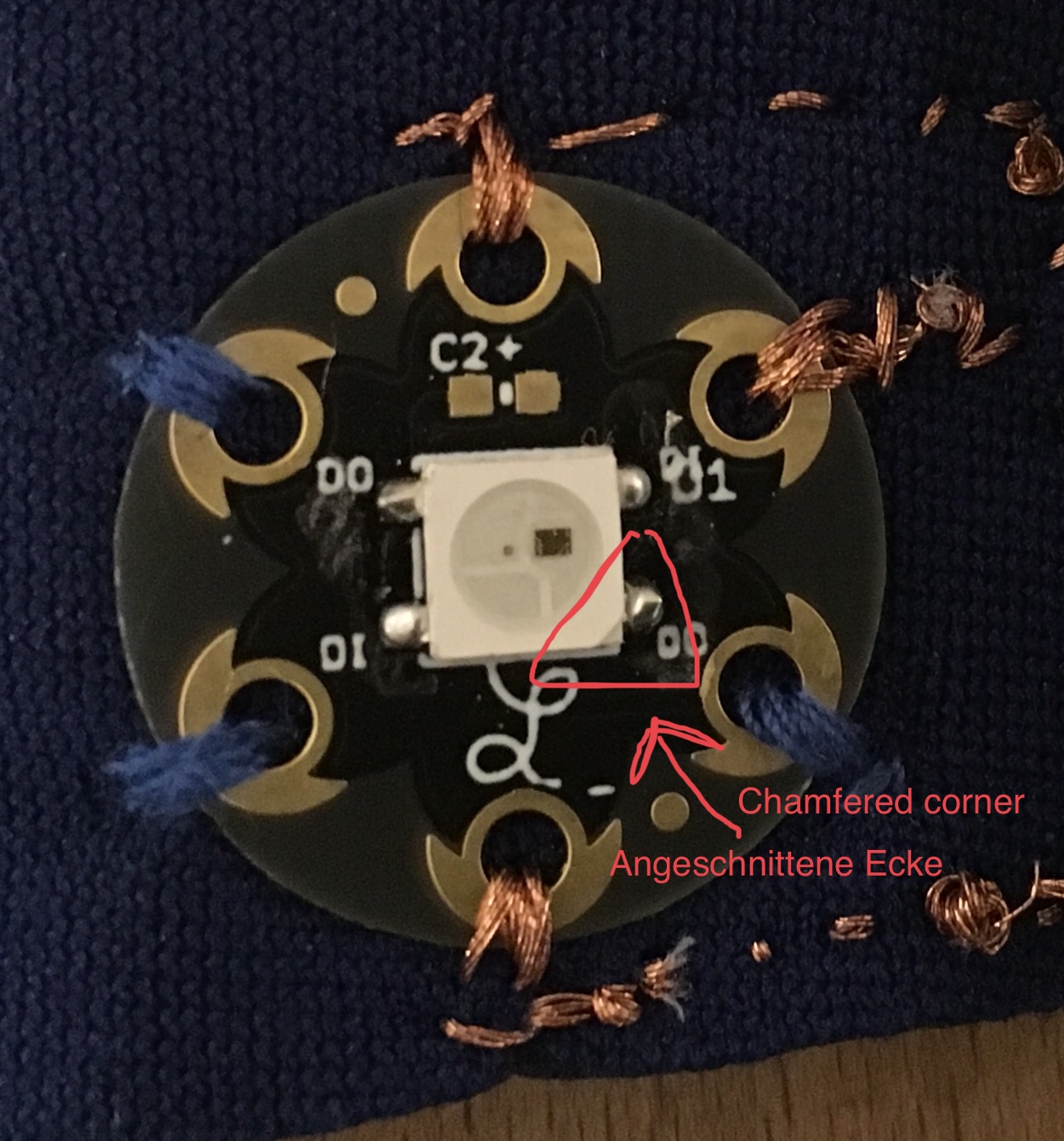
After finding the correct alignment of the LED, tin one of the solder pads on the PCB, and then solder on the LED. Continue to solder the remaining 3 pins. Heating both the pad and the pin on the LED is a bit tricky, don’t hesitate to ask for help/advice.
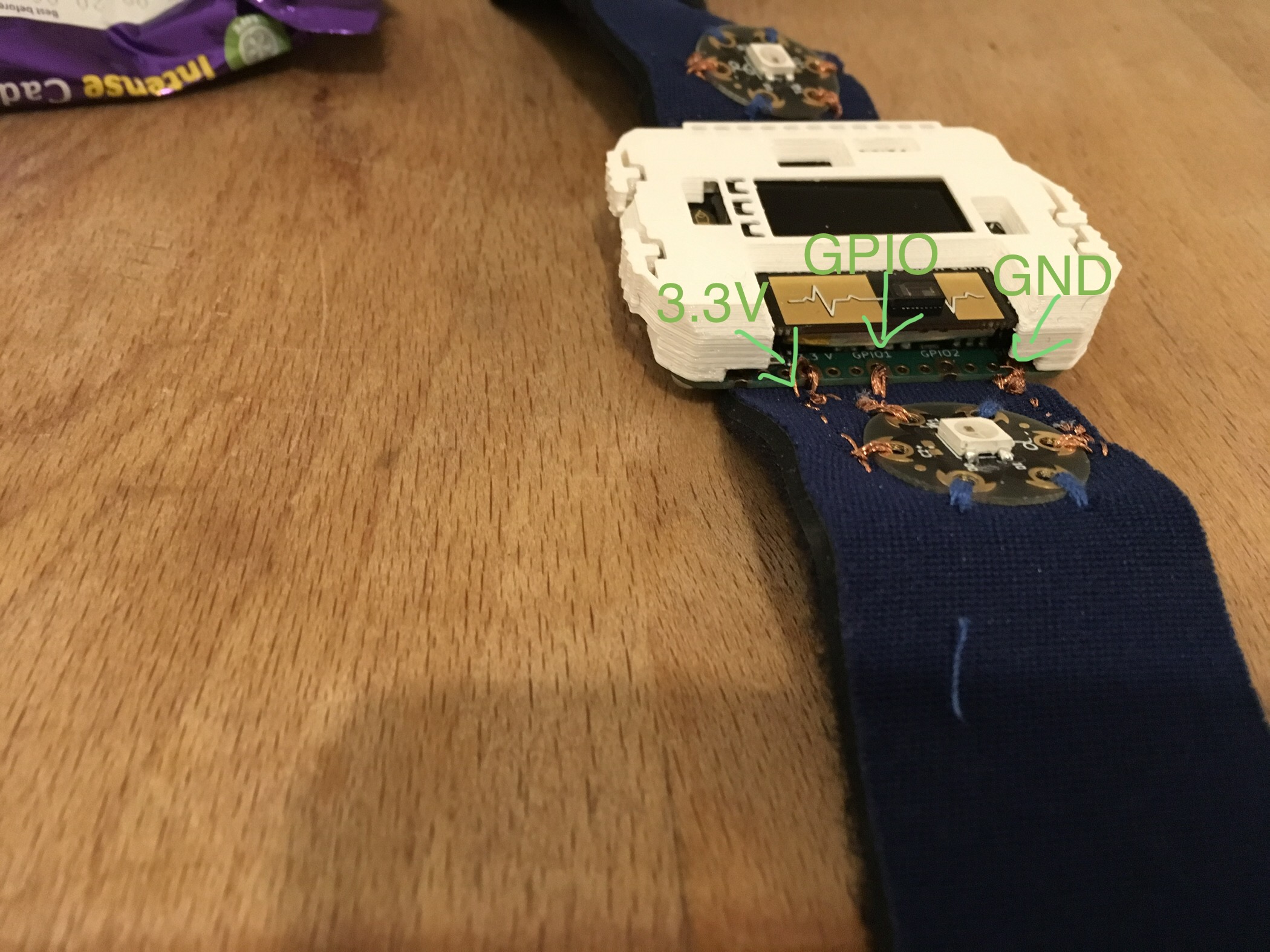
Connecting LEDs to the card10
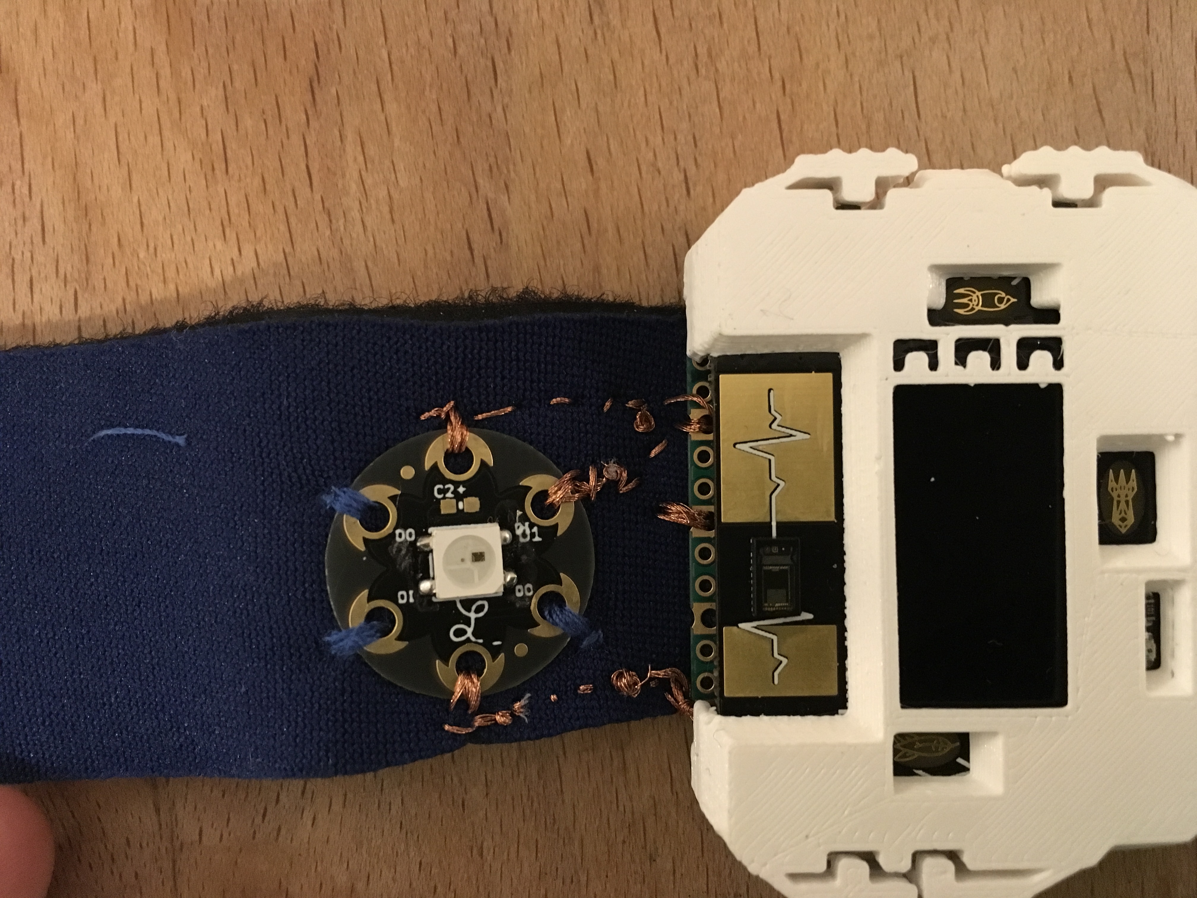
You need to make three connections from the card10 to the LED. Before you start sewing, check that the LED PCB is well aligned to the card10, so none of the sewn connections cross:
Not all 6 sewable connections are used (see below), so you can use non-conductive thread to attach the LED board with the unused sewable corners. Next we give you the connections you need to make, followed by some tips for sewing with conductive thread.
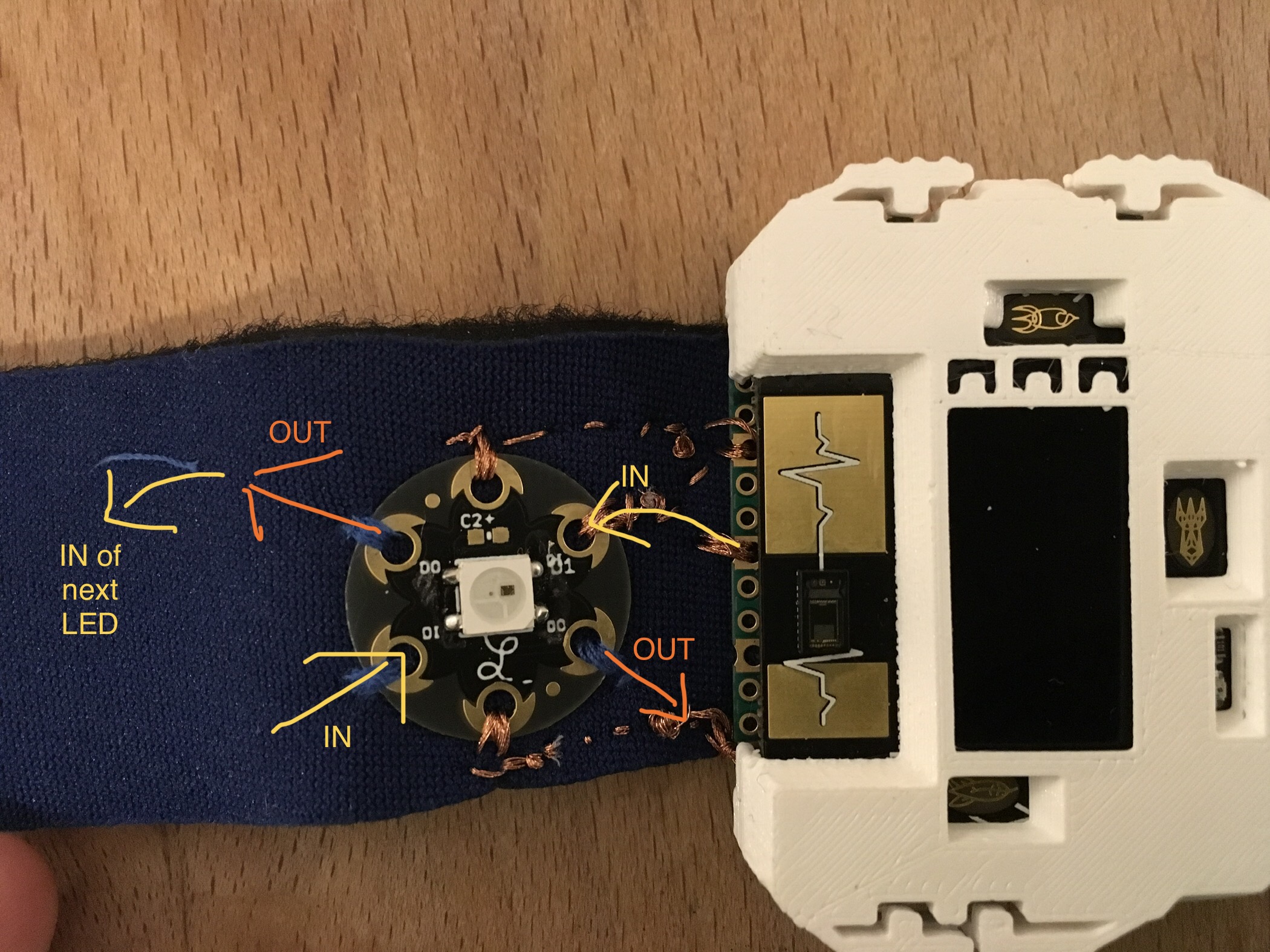
Connections
The six connections are marked in the figure below. DI and DO are duplicated, you only need to use one of each.
- GND is marked with a -, right next to the capital L
- 3.3 V is marked with a +, it is the connector on the opposite side of GND
- Data In is marked DI, pick one of the two available DI pins
- Data Out is marked with DO; you only need this pin if you are attaching a more RGB LEDs. In this case pick one of the two available DO pins and connect it to a DI pin of the next LED.
Tips for sewing
Whilst very practical, the conductivity of the thread can also be a curse when the thread gets into the wrong places. To make sure the end of your thread doesn’t short circuit the card10, first sew it onto the wristband at a safe distance. You can make a knot at the end of the thread to fix it onto the wristband. To seal the end of the conductive thread, you can add a little drop of nail polish on top of it.
While the risk of damaging your card10 is while it is sleeping, we recomment to fully switch the card10 off by holding the power/menu button for more than 8 seconds.
Please also make sure to not leave behind any conductive fibers. They might ruin someones day.
Software
The card10 firmware has support for the type of LED which the LilyPad Pixel Board uses (WS2812). It is located in the ws2812 module. See our firmware documentation for details.
Quick start
- Connect your card10 via USB
- Open a serial console to your card10 (see First Interhacktions for details)
- Press Ctrl+C to stop the current application
- Type the following code (replacing
gpio.WRISTBAND_1with the pin you are using:
import gpio
import ws2812

ws2812.set_all(gpio.WRISTBAND_1, [[25, 25, 0]])
ws2812.set_all(gpio.WRISTBAND_1, [[25, 25, 0]])
Due to a bug in the libray setting the color does not work the first time. That’s why the last line is repeated.
Your LED should light up yellow now :)
Sample application
This example queries the state of the lower right button and turns multiple RGB LEDs on when the button is pressed:
You can adjust the color, number of leds and which pin is used.
import buttons
import ws2812
import utime
import color
import gpio

COLOR_ON = color.YELLOW * 0.2 # 20% yellow
COLOR_OFF = [0, 0, 0]

LED_NUM = 1 # Number of connected LEDS: 1
LED_PIN = gpio.WRISTBAND_1

ws2812.set_all(LED_PIN, [COLOR_OFF] * LED_NUM)
ws2812.set_all(LED_PIN, [COLOR_OFF] * LED_NUM)

state = False
while True:
    if buttons.read(buttons.BOTTOM_RIGHT):
        state = not state
        if state:
            color = COLOR_ON
        else:
            color = COLOR_OFF

        ws2812.set_all(LED_PIN, [color] * LED_NUM)

        # Debounce the button
        utime.sleep(0.1)
        while buttons.read(buttons.BOTTOM_RIGHT): pass
        utime.sleep(0.1)
An example which connects the accelerometer with multiple RGB LEDs. They start lighting up when the card10 is moved:
import bhi160
import gpio
import ws2812

LED_NUM = 1
LED_PIN = gpio.WRISTBAND_1

acc = bhi160.BHI160Accelerometer(sample_rate=30)

while True:
    data = acc.read()
    if len(data) > 0:
        color = (abs(int(data[0].x * 64)), abs(int(data[0].y * 64)), abs(int(data[0].z * 64)))
        #print(data[0], color)
        ws2812.set_all(LED_PIN, [color] * LED_NUM)